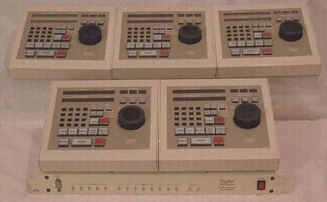
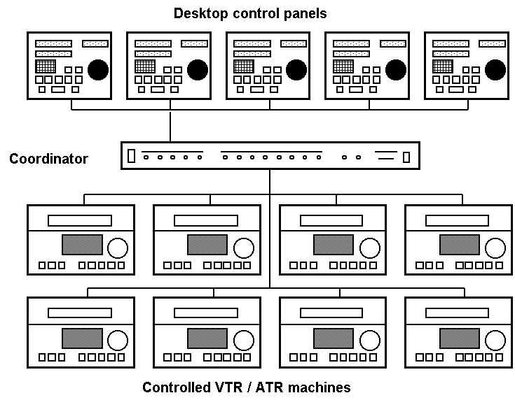
The system is centred on a 1U coordinator unit which provides serial control of eight VTRs or ATRs. This unit also has sixteen GPI lines which may be used to control secondary off-line recorders. Separate desktop panels are connected to the coordinator unit to control the machines connected to the system. Each desktop panel is able to control the operation of three machines simultaneously. A maximum of five desktop panels may be connected to a coordinator unit.
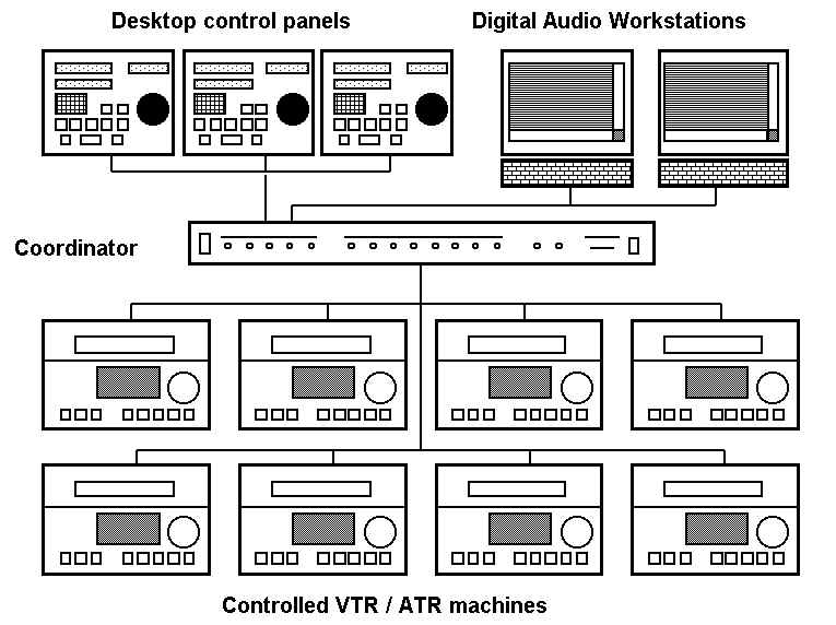
An alternative version for use with Digital Audio Workstations (DAW) in audio post-production studios is also available. This supports up to three control panels and two DAWs. Machines assigned to panel A can also be controlled and synchronised by DAW A. Similarly, machines assigned to panel B can also be controlled and synchronised by DAW B.
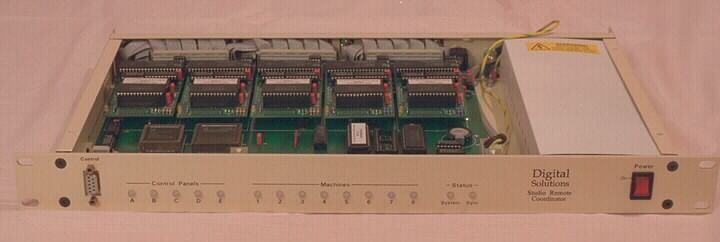
Coordinator unit
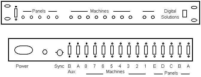
This 1U rack contains six microprocessors and fourteen RS422 9pin serial interfaces. Eight of the 9 pin ports on the rear panel are used to control the operation of machines 1-8. These ports are controlled by the central system processor via FIFO buffered UARTs. Each of the remaining rear panel 9 pin ports is directly connected to an individual sub-processor board (five in all). These sub-processors provide control and display information to the desktop control panels. The rear panel also contains connectors for the Aux A port (eight S.P.N.O. relays outputs), the Aux B port (eight logic level I/O lines), the video sync reference input, and the Mains power (100 - 240 VAC) input. The front panel of the Coordinator Rack contains fifteen tri-colour status LEDs, the fourteenth RS422 9 pin port connector, and the unit power switch.
Desktop control panels
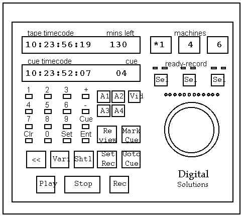
These mains powered units are each used to control up to three of the machines connected to the coordinator rack. Eighteen illuminated control keys, a sixteen key numerical keypad, and a jog / shuttle control are used to select transport modes. Cue points and other timecode functions may be modified using the keypad.
Timecode values and system status information is displayed by the three areas of dot matrix LEDs (thirty eight characters in total). The rear panel contains a RS422 connector for communication with the coordinator rack, an external command input socket, Mains input, and the power switch.
The overall size of each panel is approximately 220 mm wide,
215 mm front - rear, and 95 mm high at the rear edge sloping down
to 45 mm high at front edge.
System operation
The software developed for this system is designed to by used
by number of operators in a television production gallery, or in
multi studio post-production. Each operator has a desktop control
panel and is able to control machines for ganged record bank
program recording, isolated recording, recording review, insert
edit recording, assemble edit recording, and pre-recorded
material playback. The control of machines may be transferred
between operators as needed.
Each panel may select up to three machines to control. The
machine to be controlled is selected by holding down one of the
three SEL buttons and pressing the machine number on the keypad.
If the desired machine is already assigned to another panel a
message will inform the operator, otherwise the status of the
machine and it's current time code will be displayed. The mode of
machine operation may be select to be 'R' (recorder), 'P'
(player), or '<' (synchronised slave). Control of each machine
is enabled/disabled by pressing the appropriate SEL button. The
assignment of the machine to the panel is cleared by use of the
SEL button and the CLR key.
Various types of recording operation are supported by the system.
These include Manual Crash Record, Manual Insert Edit, Auto
Insert Edit, Auto Assemble Edit, and a special mode for studio
production recordings called 'No Over Record' which prevents the
system from erasing (recording over) any previous takes. The
operation of the system in this mode is described below.
Recording operations are enabled by selecting the machines to be
controlled, pressing the VID button to enable crash recording
mode, and then pressing the SET REC key. The system will then
perform a series of transport motion commands which ensure that
each selected machine is positioned one second beyond the last
section of program recorded on the tape. This process is designed
to ensure that it is not possible to record over any previous
program material. Whilst this process takes place the amber READY
indicator above each selected machine's SEL button will flash.
This indicator will glow steadily once the machine is correctly
positioned. When all the selected machines are correctly
positioned, the SET REC key will also become steadily lit.
Recording operation may now be initiated by pressing the PLAY and
REC keys simultaneously. A 10 second count-down is displayed to
assist the cueing of artistes. The state of each machine is
monitored throughout a recording. A red RECORD indicator above
each SEL button will glow steadily during normal recordings. This
indicator will flash if that machine reports any recording
difficulties. The timecode value of the first frame of stable
recording for each machine is stored to permit review once the
recording has been terminated by pressing the STOP key. The
record entry times for each of the last 19 recordings of each
machine are stored. The REVIEW key is used to step through this
list and locate the machine(s) to the entry point of previous
recordings.
Audio channel only INSERT recordings may also be initiated. This
is enabled by selecting the channels to be enabled for recording
by used of the A1 - A4 keys.
Machines may be controlled for playback operation. Each control
panel is able to store 99 cue points which may be used to mark or
locate sections of program by means of the MARK CUE and GO TO CUE
keys. Cue points may also be entered and revised by use of the
numeric keypad.
The VARI key enables varispeed playback. The speed of playback
may be adjusted using the jog / shuttle control whilst holding
down the VARI key. The new setting is stored for later recall.
The system provides synchronised playback or recording
facilities, and support for shared machine control with digital
audio workstations.
The control panel may also be used to set and display timecode
generator USER BITS, and to view the tape time remaining on each
machine if the controlled transport provides this information.
Special support is provided to improve the operational
performance of the controlled machines. Special functions are
provided for D-VTRs (D3, DVW), Sony BVU series, and DAT machines.
The Aux A GPI port of the coordinator unit may be used provide
howl round suppression and line-up lockout control. The system
monitors the status of machines 1-4 and uses this information
control this port.
The Aux B GPI port of the coordinator unit may be used to control
four off-line (VHS) recorders. The system monitors REC and STOP
commands as they are sent from machine ports 1-4 and uses this
information to command the off-line recorders to change mode.
The indicators on the front panel of the coordinator unit show
the communication status and machine assignments for the system.
The front panel RS422 9 pin port provides serial data display of
the timecode, transport mode, machine type, and assignment of
each machine connected to the system.
All indicators on the coordinator unit and the desktop control
panels use LEDs.
Digital Solutions (UK) Limited
109 Byewaters
Watford
WD18 8WH
Phone: (+44) (0) 1923 213233
email:
info@digitalsolutions.co.uk